1. INTRODUCTION
The centrifugation is a mechanical method of separation of immiscible liquids, or solids and liquids by the application of a centrifugal force. This force can be very large. The separations that are carried out slowly by gravity can be accelerated to a great extent with the use of centrifugal equipment.
Centrifugal or centrifugal pumps are used in different types of industries: chemical industry, petrochemical, refineries, food, pharmaceutical, textile, sugar, etc.
Spirometry is a basic test for the study of pulmonary function, and its performance is necessary for the evaluation and monitoring of respiratory diseases. Its usefulness transcends the field of pulmonology, and in recent years it is progressively being incorporated into primary care and other medical disciplines.
The spirometer is a technique for the diagnosis of respiratory diseases, because it offers a variety of data that allow a complete diagnosis. Thanks to the advancement of technology, it is easy to perform the examination, by calculating flow and volume, important variables in the spirometer technique. it is possible to determine if there is obstruction in the respiratory tract or if, on the contrary, they are in a healthy state.
List of Equipment and Materials:
- Engine
- arduino
- arduino conector
- optocuupler 4n26
- protoboard
- lcd
- transistor 2n2222
- switch
2. CONTEXTTS
During the practice a tensiometer was developed by means of a silicon pressure sensor designed for a wide range of which is the MPX5100dp, by means of the designed code the visualization of the diastolic and average systolic pressure in an LCD is allowed.
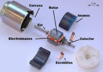
ENGINE
The DC motor (DC motor) is a machine that converts electrical energy into mechanical, causing a rotary movement. In some modifications, they exert traction on a rail. These engines are known as linear motors.
A direct current machine (generator or motor) consists mainly of two parts, a stator that gives mechanical support to the device and has a hole in the center, generally cylindrical in shape. In the stator there are also poles, which can be permanent magnets or windings with copper wire on an iron core. The rotor is generally cylindrical in shape, also wound and with a core, to which the current comes through two brushes. (National Experimental University of Táchira Department of Electronic Engineering Nucleus of Electricity Curricular Unit Electrical Technology) [3]
ENCODER
Encoders convert the movement into an electrical signal that can be read by some type of control device in a motion control system, such as a counter or PLC. The encoder sends a response signal that can be used to determine the position, count, speed or direction. A control device can use this information to send a command for a particular function. [1] (ENCODER PRODUCTS COMPANY).
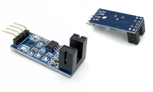
OPTOACOPLATOR
An optocoupler, also called optoisolator or optically coupled isolator, is an emitting and receiving device that functions as a switch activated by light emitted by an LED diode that saturates an optoelectronic component, usually in the form of a phototransistor or phototriac.

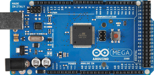
ARDUINO
Arduino is a free hardware platform, based on a board with a microcontroller and a development environment, designed to facilitate the use of electronics in multidisciplinary projects. On the other hand Arduino provides us with software consisting of a development environment (IDE) that implements the programming language of arduino and the bootloader executed on the board. The main feature of programming software and the programming language is its simplicity and ease of use. [2]
3. DEVELOPMENT

4. RESULTS
5. ANALISYS OF THE RESULTS
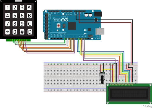
For the design of the centrifuge there were different stages. The first stage in the class session was the prototype of the centrifuge where the alarm system was installed to determine when the lid is lifted then the characterization of the encoder was proceeded, in order to observe the operation of the encoder with light and observing the variation of voltage in the output that in some cases was too short, the second stage was the programming of the keyboard so that when a number was entered it would print in order to show the revolutions per minute and time on the LCD.
I tested that the keyboard worked properly observing it on the LCD the time and the revolutions per minute correspondingly and taking out the respective calculation of the revolutions per minute in order to look at the speed at which the encoder rotates , in the third stage the part of the arduino code was added with the visualization in the LCD with the objective main to observe already the RPM in the LCD and the time (seconds) and the fixed dual power, but for this code there were too many inconveniences since the ranges that were managed to have a greater accuracy in the RPM was too difficult to calibrate that the code took too many values to get an accurate RPM but not exact, what was done as the next and last stage was to analyze the code carefully and place certain conditions so that it would not take so many values at a certain time and so with the help of the clamp an accuracy like that achieved by observing an adequate RPM value.
Finally, a positive result was obtained when observing the RPM per minute in the structure, since the code used in the Arduino was the expected one since the visualization was given correctly in the LCD without any anomaly; observing additionally on the screen both the time and the revolutions per minute according to the values chosed
6. BIBLIOGRAFY
[1]ENCODER PRODUCTS COMPANY. (s.f.). QUE ES UN ENCODER. págs. http://encoder.com/blog/encoder-basics/que-es-un-encoder/.
[2]PRENDIENDO ARDUINO. (s.f.). págs. https://aprendiendoarduino.wordpress.com/2016/09/25/que-es-arduino/.
[3]Universidad Nacional Experimental del Táchira Departamento de Ingeniería Electrónica Núcleo de Electricidad Unidad Curricular Tecnología Eléctrica. (s.f.). Conceptos Básicos de Máquinas de corriente continua. págs. file:///C:/Users/olgabeatriz/Downloads/MotoresDC-conceptosbasicos-MAPC.pdf.
