- INTRODUCTION
The electrocardiograph is a device that can capture and expand the electrical activity of the heart. It is a graphic representation of the electrical impulses of the heart and allows to measure and record the P, Q, R, S, and T wave characteristics, which vary between patients and can give the patient’s state of health. Interferences or noise on the signal register are unavoidable and are due to many causes, which can sometimes be controllable, but in others, it is therefore important to generate a system that allows the greatest cleanliness and clarity in the registry of the electrical activity. The amplitudes of the ECG depend on the connection sites of the electrodes, the size and the physical condition of the patient.
The filters are of great importance, because they are used frequently in electronic systems, the band-pass filters are those that allow the passage of frequency components contained in a certain frequency range, understood between A higher and lower frequency of cut but the Notch. or removes band filters, is the one that hinders the passage of frequency components
2. CONTEXT
List of Equipment and Materials:
• Voltage source (Dual)
• Oscilloscope
• Signal generator
• Connectors
• Multimeter
• BNC-Cayman
• 100 nf capacitor
• 10 nf capacitor
• 4 15 KΩ resistors
• Lf 353 Operational Amplifier
• The Protoboard
• Protoboard cable
• 4 Trimers
• 2 Capacitors 10 pcs
• 6 Potentiometers of 10 KΩ and 100KΩ
• 2 Capacitor 4.7uf
• Resistance of 270 Ω
• Resistance of 330 Ω
• Resistance of 1K Ω
• 10 KΩ resistance
• 100 KΩ resistance
• 4n25 optocoupler
Band Pass Filter:
The band pass filter fulfills the function of letting certain frequencies located within a certain bandwidth pass, and attenuates those that are outside this bandwidth. It is the lower cutoff frequency (f1) and the upper cutoff frequency (f2) that determine, from their position, which will be the frequencies lower than f1 and higher than f2 to be attenuated. A bandpass filter has three parameters: frequency f0, gain and Q factor related to the width of the band.[1]
Notch filter:
It is characterized by rejecting a certain frequency that is interfering with a circuit, in our case the frequency of 60Hz that is generated by the power line. The circuit is exposed to environmental noise that comes from fluorescent lamps and other devices that emit noise through 60 Hz waves. The NOTCH filter will be responsible for exclusively rejecting the 60 Hz noise to deliver a completely pure signal to the output. of distortions. [3]
3. DEVELOPMENT

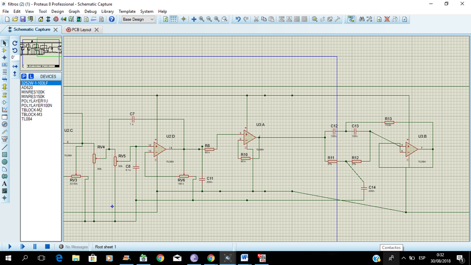
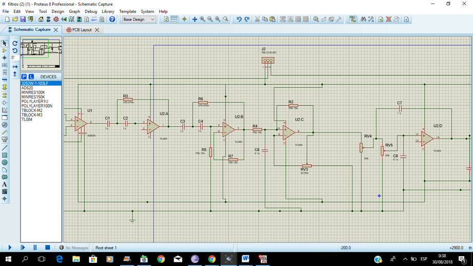
image 2. calculations capacitos, resistors and band pass filter.


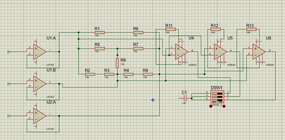
image 6. electric plane of Amplification stage and ned wilson
4. RESULTS
https://youtu.be/9i9atOk3CBE
5. GLOSARY
·cardiac pathologies
·instrumental amplifier
·ECG
·signaling
·wilson Ned
6. ANALYSIS OF RESULTS.
For the design of the bandpass filters (1-2Hz and 100-1KHz) and the Notch Filter (60Hz) respectively, the relevant calculations were carried out in order to have a greater accuracy when making the different assemblies and thus the signal input and output were expected, the filter with frequency of 1-2 Hz had complications since it handled a very low cutoff frequency, therefore what was done was to perform the filter separately, that is, it was first made the filter passes high of 100 Hz and then the Filter passes low of 1Khz, the rest for the design of the filter that went of 100 Hz-1Khz and Notch filter did not have major difficulty since when observing the signals with their distintitas attenuations were Expected a clear example that the operation was the indicated was that in the Notch filter at the time that the frequency reached 60 Hz the output signal was greatly attenuated, already with respect to the signals of the pass It works in a similar way since the frequencies that were below 1Hz were letting them pass while the frequencies that were above 2 Hz attenuated them in a perfect way in the same way it happened with the filter that went from 100-1Khz. The last one was able to observe the ECG simulator signal with its different frequencies (60, 90 and 120 ppm) in the oscilloscope satisfactorily managing the different gains of the signal with the use of the potentiometer and thus it was assumed that both the simulator and the Filters were perfect without any distortion.
Limitations
the ground: The problem and the problem are conexion a tierra, in the corollary of the corriguio, the haciendo que el paciente sujetara con una extremidad una superficie metalica.
the capacitors: For those who want to do business, they will be able to work out their own capacities and make them more productive, and you will not be able to find them in any way, nor do they have a comedy movie, and you will be able to enjoy it.
7. BIBLIOGRAPHY
[1] Electrónica Unicrom (2010). Filtros Eléctricos y Electrónicos. Recuperado (10 de febrero de 2018) de:“https://unicrom.com/filtros-electricos-electronicos-tipos-caracteristicas/” [2] Análisis de circuitos y sistemas lineales (2013). Función de atenuación. Ancho de banda y frecuencia .Recuperado (11 de febrero de 2018) de:“https://www.google.com.co/search?q=filtro+pasa+banda+definicion&dcr=0&source=lnms&tbm=isch&sa=X&ved=0ahUKEwie6IrOnZ_ZAhXPslkKHXCNBEMQ_AUICigB&biw=1707&bih=796#imgrc=TCo9Sej7MEOo2M:” [3] Blog electrónica (2015). Diseño de filtro notch. Recuperado (11 de febrero de 2018) de“http://www.electronica2000.info/2007/08/15/diseno-de-filtro-notch/” [4] Electrónica Caldas (2015). Amplificador. RecuperadoLF353 .Recuperado (11 de febrero de 2018) de“https://www.google.com.co/search?q=datasheet+lf353&dcr=0&source=lnms&tbm=isch&sa=X&ved=0ahUKEwjBuIjSrJ7ZAhWSzlkKHRHSAa0Q_AUICigB&biw=1707&bih=735#imgrc=RjwAvml1u5SVYM:”
VERY THANKS for watched this blog.Compartida públicamente
